Table of Contents
Digital IO
Pin numbers in Arduino correspond directly to the ESP8266 GPIO pin numbers. pinMode, digitalRead, and digitalWrite functions work as usual, so to read GPIO2, call digitalRead(2).
Digital pins 0—15 can be INPUT, OUTPUT, or INPUT_PULLUP.
Pin 16 can be INPUT, OUTPUT or INPUT_PULLDOWN_16. At startup, pins are configured as INPUT.
Pins may also serve other functions, like Serial, I2C, SPI. These functions are normally activated by the corresponding library. The diagram below shows pin mapping for the popular ESP-12 module.
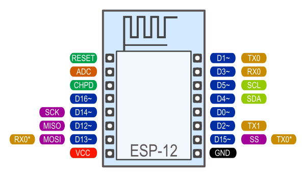
Digital pins 6—11 are not shown on this diagram because they are used to connect flash memory chip on most modules. Trying to use these pins as IOs will likely cause the program to crash.
Note that some boards and modules (ESP-12ED, NodeMCU 1.0) also break out pins 9 and 11. These may be used as IO if flash chip works in DIO mode (as opposed to QIO, which is the default one).
Pin interrupts are supported through attachInterrupt, detachInterrupt functions.
Interrupts may be attached to any GPIO pin, except GPIO16. Standard Arduino interrupt
types are supported: CHANGE, RISING, FALLING.
Analog input
ESP8266 has a single ADC channel available to users. It may be used either to read voltage at ADC pin, or to read module supply voltage (VCC).
To read external voltage applied to ADC pin, use analogRead(A0). Input voltage range is 0 — 1.0V.
To read VCC voltage, ADC pin must be kept unconnected. Additionally, the following line has to be added to the sketch:
ADC_MODE(ADC_VCC);
This line has to appear outside of any functions, for instance right after the #include lines of your sketch.
Analog output
analogWrite(pin, value) enables software PWM on the given pin. PWM may be used on pins 0 to 16.
Call analogWrite(pin, 0) to disable PWM on the pin. value may be in range from 0 to PWMRANGE, which is equal to 1023 by default. PWM range may be changed by calling analogWriteRange(new_range).
PWM frequency is 1kHz by default. Call analogWriteFreq(new_frequency) to change the frequency.
Timing and delays
millis() and micros() return the number of milliseconds and microseconds elapsed after reset, respectively.
delay(ms) pauses the sketch for a given number of milliseconds and allows WiFi and TCP/IP tasks to run.
delayMicroseconds(us) pauses for a given number of microseconds.
Remember that there is a lot of code that needs to run on the chip besides the sketch
when WiFi is connected. WiFi and TCP/IP libraries get a chance to handle any pending
events each time the loop() function completes, OR when delay is called.
If you have a loop somewhere in your sketch that takes a lot of time (>50ms) without
calling delay, you might consider adding a call to delay function to keep the WiFi
stack running smoothly.
There is also a yield() function which is equivalent to delay(0). The delayMicroseconds
function, on the other hand, does not yield to other tasks, so using it for delays
more than 20 milliseconds is not recommended.
Serial
Serial object works much the same way as on a regular Arduino. Apart from hardware FIFO (128 bytes for TX and RX) HardwareSerial has additional 256-byte TX and RX buffers. Both transmit and receive is interrupt-driven. Write and read functions only block the sketch execution when the respective FIFO/buffers are full/empty.
Serial uses UART0, which is mapped to pins GPIO1 (TX) and GPIO3 (RX). Serial may be remapped to GPIO15 (TX) and GPIO13 (RX) by calling Serial.swap() after Serial.begin. Calling swap again maps UART0 back to GPIO1 and GPIO3.
Serial1 uses UART1, TX pin is GPIO2. UART1 can not be used to receive data because normally it's RX pin is occupied for flash chip connection. To use Serial1, call Serial1.begin(baudrate).
By default the diagnostic output from WiFi libraries is disabled when you call Serial.begin. To enable debug output again, call Serial.setDebugOutput(true). To redirect debug output to Serial1 instead, call Serial1.setDebugOutput(true).
You also need to use Serial.setDebugOutput(true) to enable output from printf() function.
Both Serial and Serial1 objects support 5, 6, 7, 8 data bits, odd (O), even (E), and no (N) parity, and 1 or 2 stop bits. To set the desired mode, call Serial.begin(baudrate, SERIAL_8N1), Serial.begin(baudrate, SERIAL_6E2), etc.
Progmem
The Program memory features work much the same way as on a regular Arduino; placing read only data and strings in read only memory and freeing heap for your application.
The important difference is that on the ESP8266 the literal strings are not pooled. This means that the same literal string defined inside a F("") and/or PSTR("") will take up space for each instance in the code. So you will need to manage the duplicate strings yourself.
There is one additional helper macro to make it easier to pass const PROGMEM strings to methods that take a __FlashStringHelper called FPSTR(). The use of this will help make it easier to pool strings.
Not pooling strings...
String response1;
response1 += F("http:");
...
String response2;
response2 += F("http:");
using FPSTR would become...
const char HTTP[] PROGMEM = "http:";
...
{
    String response1;
    response1 += FPSTR(HTTP);
    ...
    String response2;
    response2 += FPSTR(HTTP);
}